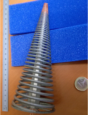
The antenna has been manufactured in Titanium with a 3D printing system for being silvered plate at the end of the process.

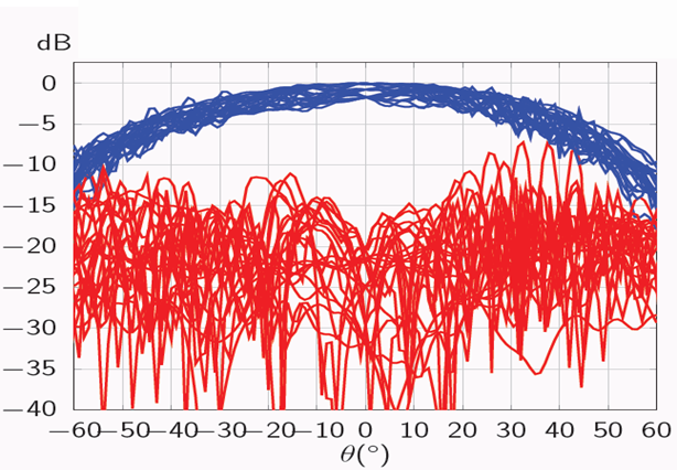
Above is shown the normalized radiation pattern of one element.
The measurement radiation patterns from 2 GHz to 14 GHz with steps of 2 GHz. Azimuth angle is 0°, 45°, 90° and 135°. The blue lines represents the copolar circular polarization level while the red lines correspond to cross-polar circular polarization. The measurements results show an agreement with the simulation results with maximum CP-XP level in broadside around 20 dB.
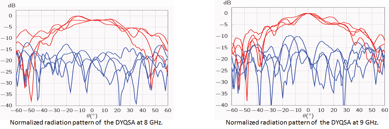
The measurement radiation patterns at 8 GHz and 9 GHz. Azimuth angle is 0°, 45°, 90° and 135°. The measurements results show an agreement with the simulation results with maximum CP-XP level in broadside > 15 dB. The response of the solution at the other frequencies is not good as there is a hard coupling between elements and central rod covering the balun. Also the solution faces a problems with stability.
An updated version of the solution is now at the manufacturing stage which solves the problem of the mutual coupling by including the four baluns at the center of the whole structure. Also the addition of a thin cone made of the liquid crystal material is performed which will totally solve the stability problem.