Radiation patterns of the feed system from 2 GHz up to 14 GHz (step of 2 GHz) at the planes φ with steps of 15º from φ = 0º up to φ = 180º. Blue line is copolar polarization and red line is cross-polar polarization. Circular polarization is assumed. Green lines remark the subtended angle from the focus of the subreflector. These results were obtained using CST and HFSS and both softwares show the same results.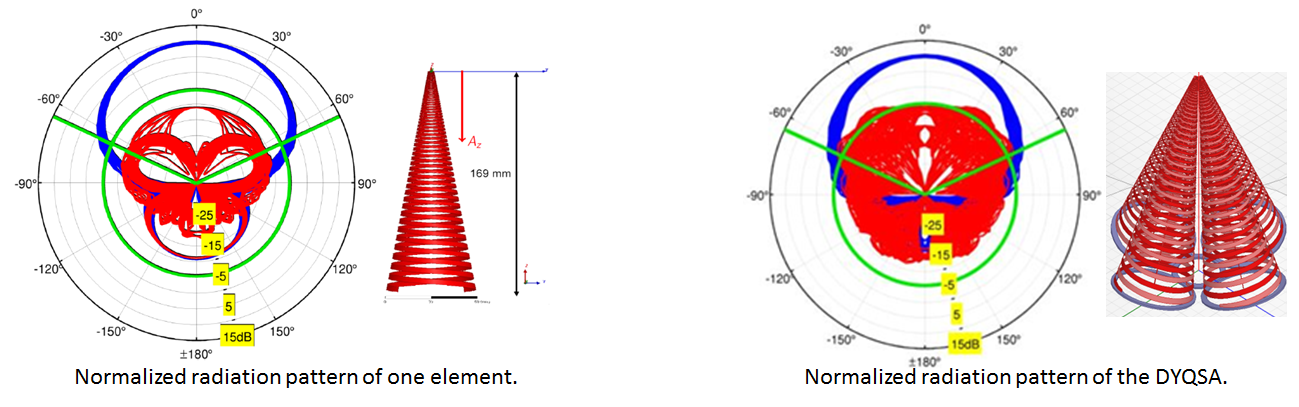
A pretty high symmetry in the radiation patterns at all frequencies is obtained with a maximum CP-XP level in broadside > 20 dB with a gain of 10 dB for the one element and a maximum CP-XP level greater than 15 dB with a 10 dB gain for the DYQSA.
The real and imaginary input impedances of both isolated element and the DYQSA are shown in the following two figures:
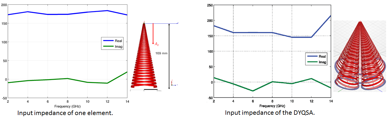
As the solution uses the self-complementary antenna so the obtained input impedance is almost real and constant. This property will simplify the design of the LNA.
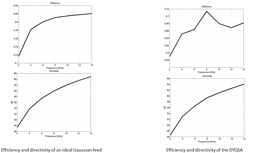
For comparison purposes, an ideal Gaussian feed is placed in the focus of the sub-reflector, using a taper of -16 dB at 65º. GRASP tool has been used for analyzing the complete system. With these first results, it is possible to have some kind of an upper limit for the total efficiency system and directivity of the radiotelescope at different frequencies.
Phase center variation along the three axes vs frequency is simulated. Az1 and Az2 are the phase center variations calculated using E-plane and H-plane radiation patterns.
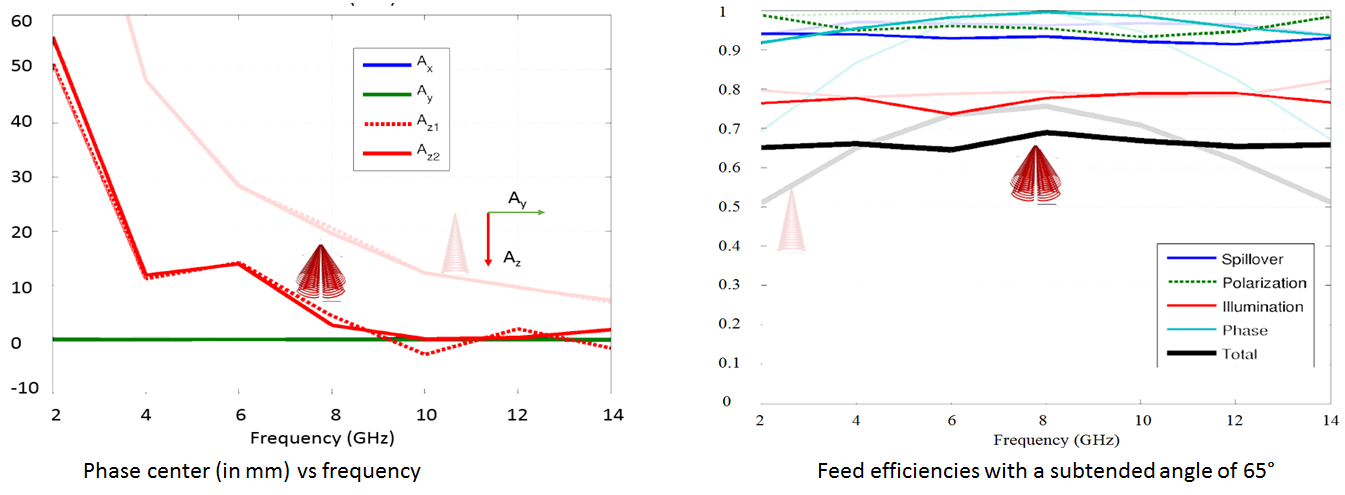
Comparison between the isolated element and the array geometry shows that the phase center variation is almost plane in the 4 – 14 GHz band for DYQSA solution. Also it is possible to find an optimum position of the feed for getting reasonable efficiencies values. In the complete solution (i.e. taking into account the two polarizations) this issue is totally solved.